Phase Distribution
The Phase Distribution Node is only shown for multiphase systems. Here, you may specify the distribution of the compounds among the phases. For compounds present in more than one phase, equilibrium distribution parameters must be provided.
Grid ViewsTabbed Views
Actions
Grid Views
Compound Distribution
Tabbed Views
Henry
Solubility
Miscibility
Permeability
Compound Distribution
This grid displays the list of compounds and allows you to specify their presence in the defined phases. The grid is organized as explained below:
If a compound has been included as measured in a phase (in the Measurements section), it must also be included in that phase here.
Top of Topic This grid displays the list of compounds and allows you to specify their presence in the defined phases. The grid is organized as explained below:
- Compound Name: In this column, all the compounds are listed.
- Phase Name(s): Check the columns (phases) where this compound is present.
If a compound has been included as measured in a phase (in the Measurements section), it must also be included in that phase here.
Henry
The view depends on the selected compound in the Compound Distribution grid, and is used to enter the Henry Distribution Parameters for the compounds that are present in both Liquid and Gas phases.
Recalling the Henry's Law:
Pi = Hi xi,
where Pi is the partial pressure of the compound i, Hi is the Henry's constant of i and xi is the molar fraction of i in the liquid phase.
The view contains two grids:
Top of Topic The view depends on the selected compound in the Compound Distribution grid, and is used to enter the Henry Distribution Parameters for the compounds that are present in both Liquid and Gas phases.
Recalling the Henry's Law:
Pi = Hi xi,
where Pi is the partial pressure of the compound i, Hi is the Henry's constant of i and xi is the molar fraction of i in the liquid phase.
The view contains two grids:
- The Henry grid, where the Henry correlation parameters are loaded.
It has the following columns: - Compound column: All the compounds which are present in both Liquid and Gas phases are listed.
- Solvent column: This is hidden by default. It is only available when option Provide Values for each solvent is selected in the Henry Parameter Calculations grid. It indicates the solvent for which the compound solubility values are provided.
- Distribution Expression column: Here, the distribution parameter is defined as a function of temperature. The temperature units in the expression are based on the chosen units in the Chemistry → Units Configuration node.
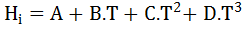
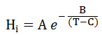
The options for the distribution parameter are:
- 3th-order polynomial correlation:
- Exponential correlation:
- Basis column: Here, you may define the phase with respect to which the distribution parameters are provided.
For Gas-Liquid equilibrium, the Basis identifies the liquid phase for which the compound's Henry parameter distribution refers to. For example, lets consider a system with two liquid phases(Liq1 and Liq2) and one gas phase(gas1), where a compound A is distributed between Liq1 and Gas1. Here, when providing the Henry parameters for compound A, you must specify Liq1 in the Basis column. - A, B, C and D columns: Are used to enter the coefficients in the expression above.
- Units column: This field contains read-only information.
For Gas-Liquid equilibrium, this column shows the units of pressure defined in the Units Configuration node (either Bar or Atm). - The Henry Parameter Calculations grid, where the options available are:
- Single Value for Reaction Mixture. This is the default option where the Henry correlation is to be applied for the whole liquid phase mixture.
For each compound present in both Liquid and Gas phases, only one row with the Henry Correlation is needed in the Henry Grid.
- Single Value for Reaction Mixture. This is the default option where the Henry correlation is to be applied for the whole liquid phase mixture.
- Provide Values for each solvent.
When selecting this option, for a given volatile species there are as many Henry correlation parameters as Solvents are defined.
Thus, the Henry parameter Hi= Pi / Xi, is calculated by summing up the Henry values among the solvents as below:
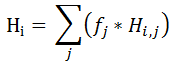
Where Hi,j represents the Henry of volatile species i with respect to solvent j, as defined in the Henry Grid. The factor that accounts for the solvents mix in the liquid phase is obtained through:
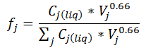
Where Cj(liq) represents the molarity concentration of solvent j in the liquid phase; Vj is the specific volume of solvent j (whose units would be lit/gmol if liter and gmol were selected in Units Configuration node).
The solvent specific volumes are calculated through density calculations.
Two options are thus available:
- Use Solvent Density Data:
By selecting this option, specific volumes of solvents are calculated based on the Molecular Weights and Density Data, which must be provided in the Chemistry → Compounds → Properties node.
- Use Solvent Density Correlation:
Specific volumes of solvents are calculated based on the Molecular Weights and Density Correlation, which must be provided in the Chemistry → Compounds → Properties node.
- Use Solvent Density Data:
By selecting this option, specific volumes of solvents are calculated based on the Molecular Weights and Density Data, which must be provided in the Chemistry → Compounds → Properties node.
Solubility
This view is available when one or more species are defined in the Compound Distribution grid to be present in both Liquid and Solid phases
The solubility relationship is expressed by the following inequality:
xi,ph <= Hi ,
where Hi is the solubility of compound i and xi,ph is its molar fraction in the liquid phase.
The view is similar as for Henry, without the Solvent column; solubilities values are with respect to the liquid mixture thus there is no need of defining parameters as a function of solvents.
Top of Topic This view is available when one or more species are defined in the Compound Distribution grid to be present in both Liquid and Solid phases
The solubility relationship is expressed by the following inequality:
xi,ph <= Hi ,
where Hi is the solubility of compound i and xi,ph is its molar fraction in the liquid phase.
The view is similar as for Henry, without the Solvent column; solubilities values are with respect to the liquid mixture thus there is no need of defining parameters as a function of solvents.
Miscibility
This view is available when one or more species are present in two Liquid phases.
The miscibility equilibrium is given by:
Hi = xi,ph1 / xi,ph2 ,
where xi,ph1 and xi,ph2 represent the molar fraction of compound i in the liquid phases ph1 and ph2 respectively, while Hi is the miscibility parameter.
The Basis indicates which of them is to be referred as the ph2 phase, that is the phase in the denominator in the above expression.
Top of Topic
Permeability
This view is available only for the Gas - Gas membrane reactor, where a given species can be present in both Gas phases.
The permeation flux of a compound through a gas membrane is given by:
Fluxi = Hi * ( Pi,rphExponent - Pi,pphExponent ) ,
where Pi,rph and Pi,pph represent the partial pressure of compound i in the reaction phase rph and the permeate phase pph respectively, while Hi is the permeability parameter.
The Permeability Values must be supplied in gmol / m2 / min / AtmExponent, independent of the project units selected in Units Configuration node.
The molar flow across the membrane is the Flux multiplied by the Specific Membrane Area. For solid catalyst, this is typically in m2/gram of solid catalyst and can change along the length of the reactor. It should be entered in Experiments → Measurements → Sets for each CSTR reactor or is interpolated from provided data for a PFR reactor.
Please note that the Membrane reactor model has limited applicability and is not supported in the following cases:
- Batch reactor
- PFR with Recycle
- For models using Mass Density instead of molar concentration.
- For Detailed Catalyst Model
Top of Topic
Actions
Quick Run
Open Solver
Top of Topic
See Also: